


Next: Myrinet Clos Network
Up: Interconnection Networks
Previous: Ethernet
Switches
- An
 switch consists of
  input ports,
  output ports, links connecting each input to every output, control logic to select a specific connection, and internal buffers.
- Although and do not have to be equal, in practice and in most cases they
have the same value, which is usually power of two. A switch is used to establish connections from the input ports to the output ports. These connections may be one-to-one, which represent point-to-point connections, or one-to-many, which represent multicast or broadcast.
- The case of many-to-one should cause conflicts at the output ports and therefore needs arbitration to resolve conflicts if allowed. When only one-to-one connections are allowed, the switch is called crossbar. An
 crossbar switch can establish
  connections (to allow only one-to-one connections, the first input port should have
  choices of output ports, the second input port will have (
 ) choices, the third input port will have (
 ) choices, and so on. Thus, the number of one-to-one connections is
 )
)
- For example, a binary switch has two input ports and two output ports. The number of one-to-one connections in a binary switch is two (straight and crossed), while the number of all allowed connections is four (straight, crosses, lower broadcast, and upper broadcast).
- Routing can be achieved using two mechanisms: source-path and table-based.
- In source-path, the entire path to the destination is stored in the packet header at the source location. When a packet enters the switch, the outgoing port is determined from the header. Used routing data is stripped from the header and routing information for the next switch is now in the front.
- In table-based routing, the switch must have a complete routing table that determines the corresponding port for each destination. When a packet enters the switch, a table lookup will determine the outgoing port.
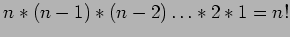
Figure 6:
Source-path routing vs. table-based routing.
|
|
Figure 6illustrates the difference between source-path routing and table-based routing in the case when a packet enters an 8-port switch at port 0. In the source-path case, the header contains the entire path and the next port is port 6. In the table-based case, the destination address dest-id is looked up in the routing table and port 6 is followed.
Next: Myrinet Clos Network
Up: Interconnection Networks
Previous: Ethernet
Cem Ozdogan
2006-12-27
![\includegraphics[scale=1]{figures/routing.ps}](img14.png)