


Next: Processor Support for Message
Up: Message Passing Architecture
Previous: Routing Potential Problems
Contents
Switching Mechanisms in Message Passing
- Switching mechanisms refer to the mechanisms used to remove data from an input channel and place it on an output channel.
- Network latency is highly dependent on the switching mechanism used. A number of switching mechanisms have been in use.
- store-and-forward,
- circuit-switching,
- virtual cut-through,
- wormhole,
- pipelined circuit-switching.
- In circuit-switching networks, the path between the source and destination is first determined, all links along that path are reserved, and no buffers are needed in each node. After data transfer, reserved links are released for use by other messages.
- An important characteristic of the circuit-switching technique is that the source and destination are guaranteed a certain bandwidth and maximum latency when communication is established between them.
- This static bandwidth allocation regardless of the actual use is the main drawback of the circuit-switching approach.
- However, static bandwidth allocation leads to a simple buffering strategy. In addition, circuit-switching networks are characterized by having the smallest amount of delay.
- This is because message routing overhead is only needed when the circuit is set up; subsequent messages suffer no, or minimal, additional delay.
- Therefore, circuit-switching networks can be advantageously used in the case of a large number of message transfers.
- The store-and-forward switching mechanism provides an alternate data transfer scheme.
The main idea is to offer dynamic bandwidth allocation to messages
as they flow through the network, thus avoiding the main drawback of the circuit-switching mechanism.
Two main types of store-and-forward networks are common. These are packet-switched and virtual cut-through networks.
- In packet-switched networks,
- Each message is divided into smaller fixed size parts, called packets, before being transmitted.
- Each node must contain enough buffers to hold received packets before transmitting them.
- A complete path from source to destination may not be available at the start of transmission. As links become available, packets are moved from node to node until they reach the destination node.
- Since packets are routed separately through the network, they may follow different paths to the destination node.
- This may lead to packets arriving out of order at the destination. Therefore, an end-to-end message assembly scheme is needed, incurring additional overhead.
- Packet-switched networks suffer also from the need for routing overhead for each packet, rather than message, sent into the network.
- In addition to dynamically allocating bandwidth, packet-switched networks have the advantage of reduced buffer requirements in each node.
- In virtual cut-through, a packet is stored at an intermediate node only if the next required channel is busy.
- Virtual cut-through is similar to the packet-switching technique,
with the following difference. In contrast to packet switching, when a packet arrives at an intermediate node and its selected outgoing channel is free, the packet is sent out to the adjacent node towards its destination before it is completely received.
- Therefore, the delay due to unnecessary buffering in front of an idle channel is avoided.
- In order to reduce the size of the required buffers and decrease the incurred network latency, a technique called wormhole routing has been introduced. Here, a packet is divided into smaller units called flits (flow control bits).
- These flits move in a pipeline fashion with a header flit leading the way to the destination node.
- When the header flit is blocked due to network congestion, the remaining flits are also blocked.
- Only a buffer that can store a flit is required for a successful
operation of the wormhole routing technique. The technique is known to produce a latency that is independent of the path length and it requires less storage at all nodes compared to the store-and-forward packet-switching technique.
Figure 6.4:
Communication latencies in the store-and-forward (SF) and wormhole (WH) techniques.
|
|
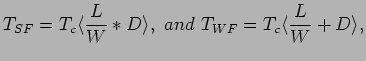
Fig. 6.4 illustrate the difference in performance between the store and-forward (SF) and wormhole (WH) routing in terms of communication latency.
- In these figures,
 represents the packet length in bits,
  represents the channel bandwidth in bits/cycle,
  is the number of channels, and
  is the cycle time. As can be seen from the figures, the latency of the SF and that of the WH are given respectively by
Table 6.5 shows an overall comparison of a number of switching mechanisms.
is the cycle time. As can be seen from the figures, the latency of the SF and that of the WH are given respectively by
Table 6.5 shows an overall comparison of a number of switching mechanisms.
Figure 6.5:
Comparison Among a Number of Switching Techniques.
|
|
Next: Processor Support for Message
Up: Message Passing Architecture
Previous: Routing Potential Problems
Contents
Cem Ozdogan
2006-12-27
![\includegraphics[scale=0.7]{figures/sf.ps}](img253.png)
![\includegraphics[scale=0.7]{figures/wh.ps}](img254.png)
![\includegraphics[scale=0.8]{figures/comparisonswitching.ps}](img259.png)